
(Spin Digit Editorial):- Dongguan, Guangdong Jul 13, 2026 (Issuewire.com) – What is a Chip-On-Glass Display?
Chip-on-glass display is a type of LCD where the driver IC is mounted directly onto the glass substrate of the screen, rather than on a separate PCB.
More on Spindigit:
- The Future of Energy Storage: Insights from a Leading China Rechargeable Li Ion Battery Manufacturer
- How to Choose the Right Method for Chip-on-Glass Driver Board Integration?
- Lithosphere Expands Agent Infrastructure for Web4 Application Growth
- Not Another Communiqué: 50+ Nations to Draft the Geneva Compact on AI Sovereignty and Sign Pooled-Compute Deals
- Sean Powers Explains Why Small Operational Improvements Often Deliver the Biggest Results
This Chip-on-Glass driver board integration offers several benefits:
- Slim Profile: Eliminates the need for a PCB to house the driver IC, saving space.
- Better Signal Integrity: Shortens the signal path between the controller and the pixels, which reduces latency and electromagnetic interference (EMI).
- Durability: The direct bonding often results in better shock resistance.
However, because the driver chip is on the glass, you must connect a bridge between the delicate pins on the display and your main controller board. This bridge is the critical part of Chip-on-Glass driver board integration, and choosing the right connection method–whether pin headers or FPC flexible connectors–directly affects the reliability and performance of your overall system.
Metal pin header connection for Chip-on-Glass Driver Board Integration
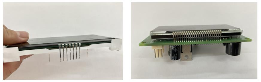
Pin headers are a basic electronic component used for circuit connection and are usually found on circuit boards of electronic devices. They provide a path for electrical connection between electronic components and have a wide range of uses, such as module connection, signal transmission, and test point setting. When it comes to Chip-on-Glass Driver Board Integration, pin headers are often considered as one of the bridging options, though they come with certain trade-offs in reliability and assembly complexity.
Connections between circuit modules: Pin headers are usually used to connect modules between circuit boards, such as providing an electrical interface between a main board and a daughter board, or an expansion board. This design allows for quick replacement and upgrade of modules, helping to improve the maintainability and scalability of the system. However, for Chip-on-Glass Driver Board Integration, the delicate nature of COG displays makes pin header soldering a high-risk operation compared to flexible FPC connections.
Signal transmission: Pin headers provide a way to transmit multi-channel signals through pin arrangement, ensuring that electrical signals are effectively transmitted between different circuit boards. For example, pin headers are an ideal choice for connection occasions that require a large number of pins, such as display interface and storage device interface. Yet in the context of Chip-on-Glass Driver Board Integration, signal integrity must be carefully evaluated, as the physical length and soldering quality of pin headers can introduce noise and impedance mismatches.
Circuit testing and debugging: During the circuit design and production process, pin headers are often used as test points. Electronic engineers can use the pin headers to insert test equipment to measure and monitor parameters such as voltage and current of a specific circuit, making it easier to debug and detect faults. This testing capability remains valuable even in Chip-on-Glass Driver Board Integration, where pin headers on the driver board can serve as diagnostic access points before the final FPC connection is deployed.
Modular design application: In the modular design of modern electronic devices, pin headers make the connection between functional modules more flexible. For example, on a computer motherboard, pin headers are used to connect different expansion cards and peripheral devices to achieve flexible hardware configuration. While pin headers excel in these general-purpose applications, Chip-on-Glass Driver Board Integration typically favors FPC connectors for production designs, reserving pin headers primarily for prototyping and test bench setups.
Advantage of the Metal pin header connection:
- Diversity and flexibility: The pin headers have a variety of specifications and arrangements to meet different circuit design requirements.
- Reliable connection: The metal pins ensure good conductivity and mechanical stability, suitable for a variety of environmental conditions.
Shortcoming of the Metal pin header connection:
- Space occupied: In high-density circuit board design, the pin header may occupy a large space, limiting the compactness of the circuit.
- Easy to oxidize and wear: The metal part of the pin header may be oxidized and worn during long-term use, affecting the reliability of the connection.
- High welding requirements: When connecting the pin header to the driver board, a welding process is required. This operation requires the welder to have certain skills and has very high requirements for welding temperature, welding time, etc. If one of the links is not up to standard, the contact point connected to the display end will expand and contract repeatedly, and this consequence will have a great impact on the transmission signal.
- High yield rate and low cost: Based on the stringent requirements of welding technology, it is easy to damage and scrap the product, increase labor costs and the cost of waste. Therefore, although this is a very intuitive and simple connection method, when considering controlling the total cost, this method may not be the best solution.
Summary: As an important electronic component, pin headers play a key role in circuit connection and signal transmission. By properly selecting and using pin headers, the flexibility and reliability of circuit design can be effectively improved to meet the needs of different electronic devices. Understanding the characteristics and usage of pin headers can help electronic engineers better design, debug and maintain circuits.
Flexible FPC connection method for Chip-on-Glass Driver Board Integration
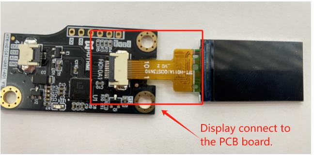
Flexible Printed Circuits (FPC) are the modern, highly preferred method for connecting COG displays. This involves a flat, flexible cable with contacts that mate to a connector on the driver board.
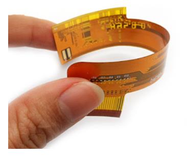
FPC-Flexible Printed Circuit is a printed circuit with high reliability and excellent flexibility made of polyester film or polyimide as the substrate. By embedding the circuit design on the bendable thin plastic sheet, a large number of precision components can be stacked in a narrow and limited space to form a bendable flexible circuit. Thin metal wires are printed on the flexible plastic strips, so they are designed to transmit electrical signals between different parts of the device. Each metal wire is an independent path for the electrical signal, and each signal carries different types of information. All signal lines are finally gathered into a row of neat metal strips, which we call “metal fingers”. These metal fingers are generally made of copper materials, which are resistant to friction, conductive, and have high hardness, so the transmission signal has good stability. When the FPC connector is connected to the device, it builds a bridge between different parts, forming a stable electrical connection. Then, when the device is turned on, the electrical signal will flow along these metal wires, so that the various parts of the device can communicate with each other. For Chip-on-Glass driver board integration, FPC is widely regarded as the preferred connection method because it eliminates the need for soldering directly onto the fragile glass substrate, significantly reducing assembly risks. In fact, the flexibility and reliability of FPC make it the industry standard for Chip-on-Glass driver board integration, especially in compact display applications where space is limited and signal integrity is critical.
Advantages of FPC
- Flexibility
Flexibility is the biggest advantage of using flexible printed circuit boards, which can be bent, folded, and rolled freely, and are easy to connect; they can be moved, stretched, and arranged at will. It is easy to reduce the size of electronic products. Because the FPC board is elastic, it can be easily placed around the edges and boards. Flexibility also requires little or no wiring in the connection, which eliminates faults in the wiring connection and improves the reliability of the equipment.
- FPC connector is light and saves a lot of space
Compared with PIN cables, displays with FPC are more than 60% lighter. This makes storage and installation easier and more convenient. They can be bent, twisted and folded, which is a very beneficial feature in complex and tightly fitting assemblies.
- FPC connectors can withstand more bending cycles
The standard materials used in FPC cables can withstand up to 200 bending cycles.
- Anti-vibration performance of FPC connector
Because the FPC board is flexible and lightweight, it can absorb vibration and effectively reduce its impact on the connection.
- FPC connectors can withstand harsh environments
FPC connectors can be made of corrosion-resistant, moisture-proof, waterproof and shock-proof materials, making them suitable for use in harsh operating environments.
- FPC connectors can be used for high-power applications
FPC connector boards are loaded with thick copper layers for high-power applications. Flexible boards are suitable for surface mount technology. (SMT) Since FPC boards are able to provide strain-free bonding sites for SMT components, they are ideal for use in SMT applications. The flexible base absorbs thermal stress, reducing the chance of solder joint failure.
- FPC connector can bend dynamically
FPC boards can flex more than flat ribbon cables. Therefore, they are the preferred connector type to provide reliable interconnects for applications that require millions of flexes, such as interconnections between moving parts.
- Reliability of FPC connector
The routing on the FPC board is determined by the artwork, eliminating the possibility of wiring errors. This translates into highly reliable interconnects.
- FPC connectors are cost-effective
With FPC, the finished component packaging size is smaller and the material cost is lower. In addition, wiring errors are reduced, which shortens the test time and reduces additional costs. Thirdly, compared with metal PIN headers, FPC does not require welding, thus reducing labor costs and the cost of scrapped products due to poor welding technology.
- Easy to install
Thanks to its simple and refined structural design, the installation and disassembly of FPC connectors are very convenient. It is widely praised in the industry. In summary, FPC connectors are light and thin, highly integrated, have high-quality electrical performance, long plug-in life, solid and reliable structure, and are easy to install.
How to Choose the Right Method for Chip-on-Glass Driver Board Integration
Now that we understand these two connection methods and their advantages and disadvantages, what is the most suitable connection method for COG displays?
As we all know, COG – Chip On Glass, refers to assembling the chip onto the LCD screen. This method makes the screen structure look simpler, small in size, and has good shock resistance. Therefore, COG is widely used. The PIN definition derived from COG contains a line with a signal, which affects which type of connector is used to lead out the signal.
Use metal pin connector: As described above, this method requires the use of welding to connect the display to the driver board. If the welding technique is not up to standard or the operation is wrong, the contact point on the LCD end will expand and contract repeatedly. Because these pins represent signal lines, if one of the metal PINs is damaged, it will cause the entire COG display to be abnormal, making repairs difficult.
Use flexible cable FPC connection: no welding is required, only a simple assembly process is required, avoiding the risks brought by metal PIN.
To sum up: If you have very good welding technology, you can use metal PIN needles between COG and its driver board, but the risk is high. Once a needle is welded wrong, the entire COG will not work. Using flexible FPC is the best choice for high-quality COG display products!
Source : Hotdisplay Technology Co., Ltd.
This article was originally published by IssueWire. Read the original article here.